Cat's Eye 2
Status: in development
I have now officially started development of the Cat's Eye 2. The Cat's Eye 1 seems to be pretty well as far as I can, or want to, go in the development of a fly-anywhere aerial photography plane with tilt and shutter control for the camera.
The next obvious step is to add a video downlink. Most still cameras have a "video out" which is essentially what you would see on the camera's screen, output as composite video. The simplist downlink scenario would be to just take this video feed and send it to the ground, as a "high-tech viewfinder". This would certainly assist in lining up shots. I could then think about adding tilt and/or pan capability or possibly even FPV, a separate video camera, etc.
There are two ways to approach this. First I could use the "incremental" approach, design plane after plane each with a bit more functionality, until I finally arrive at the plane I want. The second approach is to go straight to the "ultimate" plane in first place, and correct those things that don't work exactly as planned. I think the latter approach is probably the easier, faster and cheaper of the two. As long as it's built in a modular fashion, I can modify or replace the parts that don't work, once I get something in the air and try it out.
Concept
The Cat's Eye 2 is shaping up to be somewhat bigger than the Cat's Eye 1; probably about the size of my Long-Nose Getter. In fact, I'm hoping to use the Getter wings.
It will have:
- Video downlink
- Still camera
- VIdeo camera
- Both video and still cameras on the same pan/tilt platform
- 180º pan (full left to full right) and 90º tilt (horizon to straight down)
- View either video camera or still camera output on downlink
- Still camera shutter (and maybe zoom) control via Infrared control
Pan/tilt mechanism
As with the Cat's Eye 1, I designed the plane around the camera in a layered approach. First I considered the camera itself, followed by the camera mount, then the infrastructure to support the mount, and finally the rest of the plane.
In the case of the Cat's Eye 2, there are two cameras, a still camera and a video camera. For several reasons (including the possibility that the video downlink will be used to fly the plane, FPV-style), the cameras will look forward, rather than to the side as with the Cat's Eye 1. However, I wanted also to be able to pan to the sides as required to get "the shot."
I started with essentially the same camera mount as the Cat's Eye 1. Since I have been fairly happy with the Pentax Optio S10, I will stick with that for now. I then added the video camera, a KX-171. The video camera points the same direction as the still camera, so what you see in the video camera will give you a good idea what the still camera sees.
The mount is pivoted on both sides, for the "tilt" portion of the pan/tilt mount. I considered having the tilt servo fixed, as per the Cat's Eye 1, but decided to mount the servo on the camera mount instead, reducing the width, and thus surface area presented to the air stream.

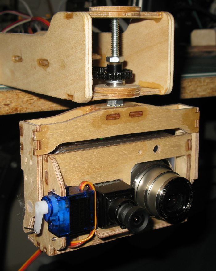
Figure 1: Pan/tilt mechanism with still and video cameras
Figure 1 shows the completed pan/tilt mechanism. (Note the Infrared LED is missing; the hole for it appears just above the still camera lens.)
To implement the "pan" function, I have to rotate about the vertical axis. I considered having the pivots both top and bottom, or bottom-only, but decided on top-only so that the cameras can be tilted to have an unobstructed view straight down. (This impacts the design of the airframe as well!)
A little secret: this is actually the second iteration of the pan/tilt mechanism. On the first one, the right-hand pivot was actually the servo bearing itself. This had the benefit of simplicity, but unfortunately the centre of gravity ended up well behind the pivot point. So much so that it would overcome the static friction of the servo, which caused it to "chatter" to maintain its position. This in turn would introduce motion blur into the photos (ask me how I know!).
I could not move the servo back as the still camera is there, so this version of the camera mount has the servo in front of the bearing, as shown, and has a short length of pushrod to the frame. This animation shows the operation of the tilt servo.

Figure 2: Animation of tilt mechanism
I wanted 180º rotation in pan which meant gearing up the 140º of a standard servo. This was done using a 30-tooth gear on the servo and 18-tooth gear on the camera platform axle, a 3/16" carriage bolt. A plastic chain runs between them. The servo is on a movable rail. The screws for the servo rail are in slots, and once the servo is positioned so the chain is tight, the screws are tightened.

Figure 3: Gears and chain for pan mechanism
The lower bearing is a ball bearing with a 5mm inside diameter (a shade larger than the 3/16 bolt). This is probably overkill for this application, but since I had one floating around, might as well use it. The pulley is actually 1/4" inside diameter. I got lucky. I found a bit of 1/4" brass tubing and tapped a thread in it that fits the 3/16" bolt. It's held in place with a nut tightened against it, and the gear goes over it.
Continue to: page 2 - Electronics


